Image ?: Main parts of yagi antenna.
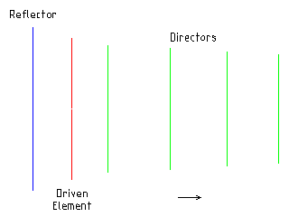
The design of a yagi antenna is much more complex and requires a lot more experimentation then a monopole antenna. I don't believe there is any known simple mathematical formula that can be used to design a yagi antenna. Am I correct?
What we do have is a rule of thumb which gives a start pointing when designing a yagi antenna. The idea is to scale up the reflector element by about 5% over the driven element, and to scale down the first director elements by about 5%, and to scale down again by about 5% for each extra director. The spacing between each of the elements would be about 20% of a wavelength, these can also be scaled down for each director.
Using this starting point you can adjusted each of the elements lengths and there offsets until you find the best preforming design. These adjustments can be easily and quickly made using antenna design software.
The result of a number of days of tweaking lengths and offsets can be found in the following nec file, gsm-900_6element_yagi.nec. I also have other nec files for the different gsm bands, gsm-550_6element_yagi.nec, gsm-1800_6element_yagi.nec and gsm-1900_6element_yagi.nec.
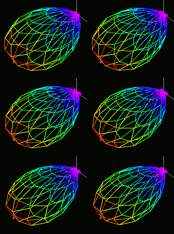
The animated image shows the radiation pattern of the antenna, the gain varies from just under 9 dB to over 10 dB over the frequency range 876 MHz to 960 MHz, covering the three main GSM-900 bands. The design also shows good VSWR (Voltage standing wave ratio) and F/B (Front to back) Ratio.
Image ?: Animated GSM-900 Yagi Radiation Pattern (876 MHz to 960 MHz).
Construction
There is room for flexibility in the construction techniques you can use. I experimented with different options for the beam including, drilling holes for the elements in wood and plastic (I was disappointed with the accuracy), using a custom printed circuit board (this worked for the prototype but would not be suitable for others to build).The technique I will show here uses solid brass rods of the elements and a wooden beam made in two half's. The two half's have small recesses which help hold the elements in place, and everything is permanently held together with strong glue.
Image ?: Yagi antenna showing each elements label.
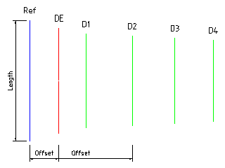
| Element Label | Offset from Ref | Element Length |
|---|---|---|
| Ref | 0 mm | 171 mm |
| DE | 41 mm | 149 mm (2 * 74.5 mm) |
| D1 | 79 mm | 132 mm |
| D2 | 144 mm | 127 mm |
| D3 | 204 mm | 120 mm |
| D4 | 258 mm | 114 mm |
- Materials (Image)
- 1 @ 3 mm diameter Brass Road 850 mm in length (thick copper wire would be a suitable alternative) 2 @ 10 mm rectangular Wooden Batten 400 mm in length 1 @ 500 mm length of 50 Ohm coax cable and suitable SMA or N connector (I used Times Microwave LMR-195) 1 @ GSM 900 template Adhesive tape Epoxy resin adhesive Cable ties
- Tools (Image)
- Hacksaw Soldering iron and solder Drill with bits Selection of hand-file's Craft knife Rule and pencil (I would suggest these as the minimum tools but extra would be helpful such as a vice, etc)
- Step 1
- To make the elements mark and cut the brass rod into seven pieces the required lengths are given in the table above and on the template sheet. Cut the elements slightly longer then needed and then file the ends down to the correct length.
- Step 2
- Use the adhesive tape to stick each of the elements in the correct location on the template sheet. The two rods that make up the driven element need to have a small gap between them.
- Step 3
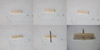
- The next step is to make the beam which will hold all the element in the correct position. The idea is to make a recess for each of the elements and then glue them into position. Mark a line for each element, you can use the template as a guide. Saw into the wood about 1 mm in depth. Use a small round file to form a semicircle recess of the element. By making two half's the element can be tightly held in place.
- Step 4
- Drill a hole in the driven element recess in one of the beam parts the same size as the coax cable diameter. Then Feed the coax through the hole. Using the craft knife trim about 15 mm of the plastic insulation from the coax. Unwrap the metal braid, twist and pull to one side, trim the excess and cut away the metal foil layer. Bend the center conductor to the opposite side. Make sure the center conductor doesn't touch the metal braid or metal foil.
- Step 5
- File two flat surfaces about 5 mm long at the center of the drive element. Trim the twisted braid and center conductor to the correct length. Solder the twisted braid to one of the drive element rods and the center conductor to the other. Check to made sure that there is no bridged joint between the rods.
- Step 6
- Mix up a small quaintly of the epoxy resin adhesive (follow the manufactures instructions for mixing and setting times). Place some of the adhesive into and coat each of the recesses on the drilled half of the beam. Place extra adhesive around the joint between the drive element rods. With the template on a flat surface, carefully place the drilled half of the beam onto template, use heavy objects to apply pressure while setting. Check that all the elements and beam are correctly positioned and leave to set.
- Step 7
- Once the adhesive is set, remove the template and carefully remove any extra adhesive which may have accumulated around the elements.
- Step 8
- Mix up a larger batch of the epoxy resin adhesive. This time apply a layer of the adhesive to the recesses and the two surfaces of the beams. Apply pressure using heavy objects or clamps, check the positioning and leave to set.
- Step 9
- Once the adhesive is set use the cable ties to secure the coax cable. This forms a strain relief and protects the drive element joints from fatigue.
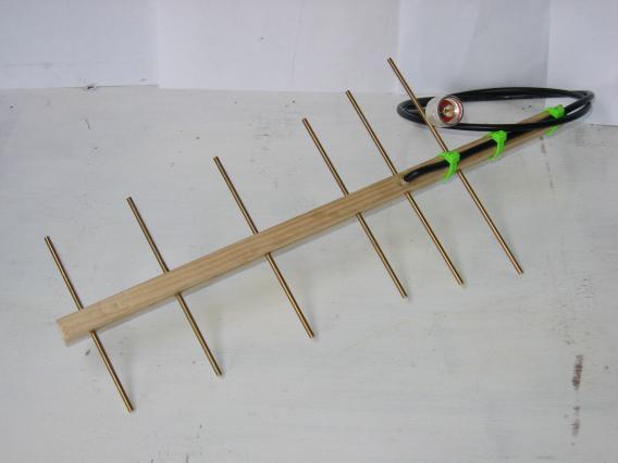
Image ?: The finished GSM-900 6 element yagi.
Antenna testing
The following image (from a USRP) shows the difference between the monopole antenna and the yagi antenna for a weak BTS signal at 937.8 MHz. The monopole is on the left and the yagi on the right.From looking at the image I would suggest that in this test the yagi has between 4 and 6 dB gain over the monopole antenna. I think the main improvement is shown in the directionality. In the upper left a large signal is shown at about 1.2 MHz above the center frequency, in the upper right image this BTS signal is attenuated by about 15 dB. Though the signal at about 1.6 MHz seems to have had an increase in gain with the yagi antenna.
The test in Image ? shows a local strong BTS signal but there is no noticeable improvement in the signal strength.
The test in Image ? shows another BTS with a small improvement in signal gain, but quite a marked improvement with 4 BTS signals being significantly attenuated.
For an absolute gain test you would need a signal generator, field strength meter and an RF shielded environment, which I don't have access to. Another option would be to do a test outside with clear light of sight between the test antenna and the BTS, I might look into this at some point.
Templates for other frequency's
Europe, Middle East, Africa and most of AsiaGSM 900 template
GSM 1800 template
Americas
GSM 850 template
GSM 1900 template
All templates should print fine on ISO A4 or US Legal sized paper.
Conclusion
The construction is relatively straight forward requiring only minimal materials and tools. I think this yagi antenna design offers some real advantages over the monopole antenna design or simple wire antenna.from (http://273k.net/gsm/designing-and-building-a-gsm-antenna/yagi/)




Tidak ada komentar:
Posting Komentar